What are Electrical Shop Drawings and How to Read Them?
Introduction
Did you know that understanding an electrical shop drawing can prevent costly errors during construction projects? These essential documents serve as detailed guides for electricians, contractors & engineers, ensuring smooth and accurate installations. But what exactly are electrical shop drawings & how can you learn to interpret them correctly? Electrical shop drawings are critical in ensuring accuracy during installation, as they are derived from detailed electrical design services provided by different engineering firms. This guide will explain everything you need to know.
What is an Electrical Shop Drawing?
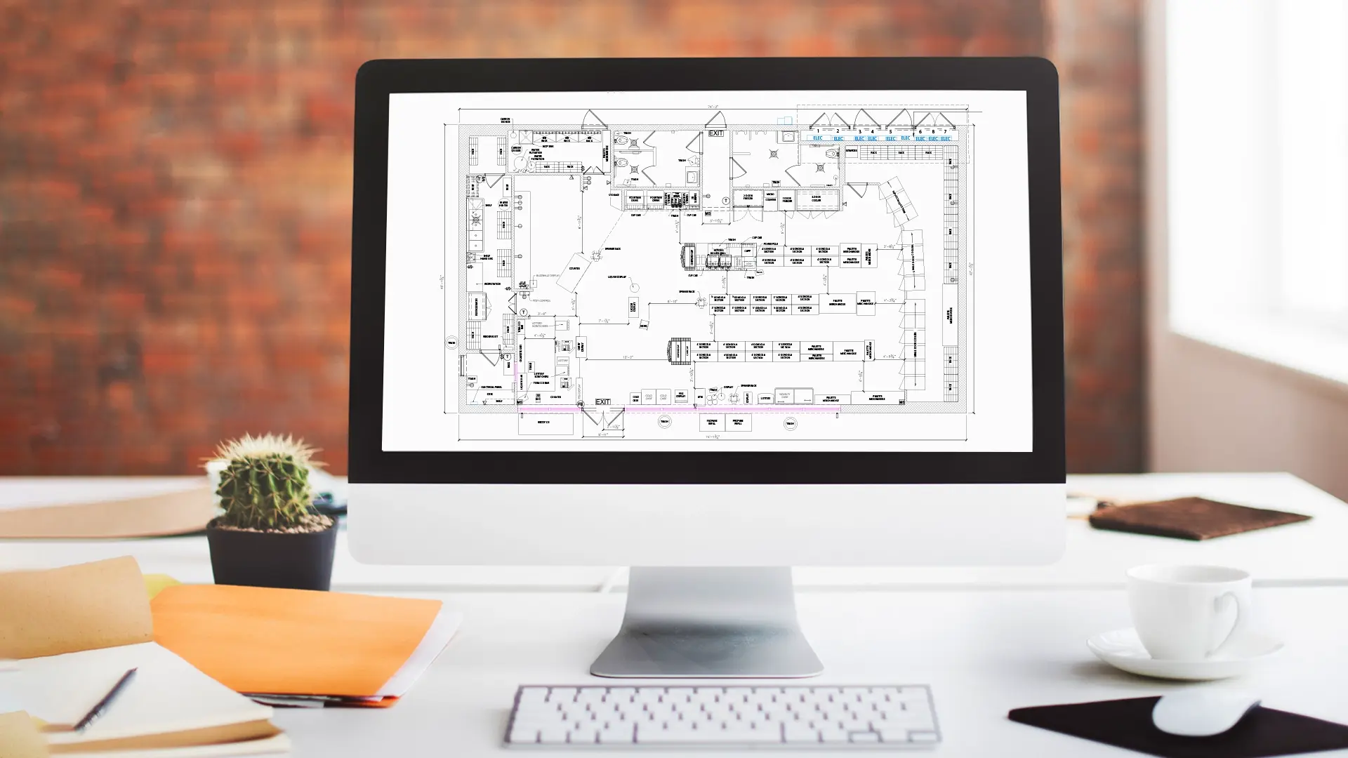
Electrical shop drawings are detailed, technical representations of a building’s electrical system. These drawings provide a detailed and descriptive visual of the electrical components, wiring layouts & connections that need to be installed on-site. Unlike schematic diagrams, which offer a general overview, shop drawings are highly specific and include accurate dimensions custom-made to your construction project.
Key Features and Elements of Electrical Shop Drawings
- Symbols and Notations – These represent different electrical components, such as switches, outlets & fixtures.
- Wiring and Conduit Layouts – These show how the electrical wires and conduits are routed throughout the building.
- Panel Schedules – Detailed information about circuit breakers, panelboards & load distribution.
- Site-Specific Details – Measurements, locations of components & installation notes customized for the project.
Electrical shop drawings are important because they ensure accuracy, improve communication among project teams & prevent errors during construction. These drawings are often part of larger MEPF Drawings Services, ensuring proper coordination between electrical systems and other critical building services such as plumbing and HVAC.
What is the right way to read Electrical Shop Drawings?
Reading electrical shop drawings may seem difficult at first, but by breaking down the process into steps, anyone can learn how to read electrical blueprints effectively.
Getting to know the basic Symbols
Electrical shop drawings use a standard set of symbols to represent various components. Familiarizing yourself with these symbols is the first step in understanding how to read electrical drawings. Common symbols include –
- Switches – Often represented by an “S” with a line or an arc.
- Outlets – Shown as a small circle with two or three lines.
- Lighting Fixtures – Depicted as a circle with an “X” or a specific fixture symbol.
By learning these symbols, you can quickly identify the components in the drawing and understand their function.
Understanding the pattern
Electrical shop drawings follow a structured layout that represents real-world installations. Begin by identifying the main power source – usually the Main Distribution Panel (MDP) – and trace circuits branching out to various systems like lighting, outlets & HVAC. Each circuit is labeled with information such as wire gauge, conduit size & breaker ratings.
Pay close attention to power distribution patterns and branch circuit layouts. Power flows from the main panel to individual loads & circuits are often grouped by type (e.g., lighting or power). Tracing these circuits helps you visualize how electricity is distributed throughout the building.
Tip – Always check the legend for symbol explanations and special notations. This ensures you correctly interpret the patterns and connections.
Understand Names and Values
Each component on a shop drawing is labeled with a name and corresponding value. Names, such as CB for Circuit Breaker or XFMR for Transformer, help identify components, while values, like “CB 20A, 240V”, indicate essential specifications.
Pay attention to:
- Conduit Sizes – Ensure proper wire routing and protection.
- Wire Types – Specify insulation type and gauge (e.g., THHN, Romex).
- Load Ratings – Help calculate circuit load to prevent overloading.
By understanding these labels, you can ensure that components are compatible and installed correctly, minimizing errors during construction.
Getting to know the details
Beyond symbols and patterns, electrical shop drawings often include fine details about the materials and installation process, such as:
- Conduit Types and Sizes – Specifies whether the conduit is metal or PVC, and its diameter.
- Wiring Types – Indicates the type of cable used, such as THHN or Romex.
- Grounding Systems – Details about grounding conductors and connections to ensure safety.
Carefully reviewing these details helps ensure compliance with electrical codes and standards, minimizing the risk of errors or safety issues.
Importance of Electrical Shop Drawing?
Electrical shop drawings are more than just technical blueprints – they’re essential tools for ensuring a project’s success.
- Accuracy
Shop drawings provide precise, site-specific details, ensuring that installations match the design intent perfectly.
- Improved Communication
They act as a common reference point for architects, engineers & contractors, reducing the chances of miscommunication.
- Material Procurement
By listing exact specifications for wiring, conduits & components, they make it easier to procure the right materials in the right quantities.
- Quality Control
Shop drawings serve as a checklist for inspectors and project managers, ensuring that installations adhere to code and design standards.
- Troubleshooting
Post-construction, these drawings help electricians troubleshoot issues efficiently by providing a clear overview of the electrical system.
Without electrical shop drawings, the risk of errors, delays & rework increases, which can significantly impact project timelines and budgets.
Conclusion
Mastering how to read electrical shop drawings is a vital skill for any construction professional. By understanding the symbols, patterns, names & values in these drawings, you can ensure that electrical installations are accurate, safe & efficient. Whether you’re a beginner or an experienced contractor, investing time in learning to interpret these diagrams will improve your project outcomes and reduce costly mistakes.


